|
Installation Instructions
Field Measurements
- Allow for wall panel Thickness on one leg of an intersecting wall when measuring an inside corner.
- For an outside corner, the panel on one wall must be extended beyond the wall to meet the Thickness of the panel on the adjoining wall so as to form a perfect corner.
- When installing panels using "Z-Clips, a clearance of 3/4" at the top of the top most panel must be allowed for in order install panels.
"Z"-Clip Mechanical Mounting Installation Instructions
When to use the "Z"-clip mounting method
The "Z"-clip mechanical mounting method is used when you have large panels that you would like to be removable. This method is much like hanging a picture on the wall. The clips allow the panels to be easily lifted off or set on the wall.
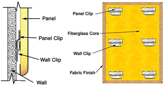
 Panel Section at Z-clip mountingZ-Clip Detail Panel Section at Z-clip mountingZ-Clip Detail
"Z"-Clip Installation
- With back side of panel facing up, lay wall clips into panel clips.
- Measure from top of panel to bottom of wall clips. (Refer to detail).
This will give dimension of bottom of wall clips to desired panel height.
- Snap chalk lines on wall at indicated heights.
- Attach wall clips to wall with bottom of clip at chalk lines. (See notes 1, 2 & 3)
- Place panel on wall at least ¾" (three quarter inch) higher than desired height and press firmly against wall. Slide panel down to engage clips. Check to be sure all clips are engaged.
Notes:
- On gypsum board walls Where it is impractical to screw through to studs use of appropriate screw anchors is recommended.
- Powder actuated devices are most economical. Where this is impractical a screw anchor must be used.
- On Wood or Steel walls: Clips may be screwed directly to the wall.
Hook and Loop Fastner Installation Instructions
The hook and loop fasteners (i.e. Velcro) are used to secure Acousticore panels to clean, smooth, non-porous surfaces. This system should always be applied by using either contact cement, or with a staple gun purchased at a local hardware store. The adhesive that is already on the back of the Velcro pieces WILL NOT hold up the panel alone. CONTACT CEMENT OR STAPLES MUST BE USED! SPRAY ADHESIVES ARE NOT AN ALTERNATIVE!
Material:
When this technique is specified, Acousticore wall panels are furnished with factory-applied loop Velcro on the backside of the panel. For each patch of loop Velcro there is an accompanying length of hook Velcro.
Method:
- Loop Velcro strips are uniformly positioned on the rear of like-size panels at the factory.
- Installer is to insure wall surfaces are smooth, clean and non-porous.
- a. Determine the appropriate positions for hook tape.
b. Apply contact cement to the wall where the Velcro will be applied, let the contact cement dry according to the manufacturers directions. Then remove release paper and press firmly.
- Remove release paper from the hook Velcro and press Velcro very firmly to wall. All entrapped air must be removed. (DO NOT apply hook Velcro to panel back, remove release paper and run panel to wall)
NOTE: A small roller, the size used for wallpaper seams works well.
- Wall panel is then firmly pressed against wall engaging the loop Velcro on the panel back to the hook Velcro on the wall
- If repositioning or removal of the panel is necessary, the panel must be "peeled" from the wall if at all possible. A thin, flat, rigid blade is useful in starting the break in the bond between the panel and the loop Velcro, the hook Velcro and the wall, or both.
- Some panel facings may soil easily. Therefore, appropriate care must be taken. Installer should have clean hands or wear clean gloves.
NOTE: These instructions serve only as a guide. There are many variable field conditions, the responsibility for recognizing these conditions and compensation for them lies with the installer.
|